GES Modules
GES 3D Modeling
Scale Up Structure
Before upscaling the model, the grid system needs to be coarsened in the first place. It is unnecessary to maintain similar stratigraphic framework and geometry between the finer and coarser grid system. However, a better similarity would shorten the time require to upscale the model.
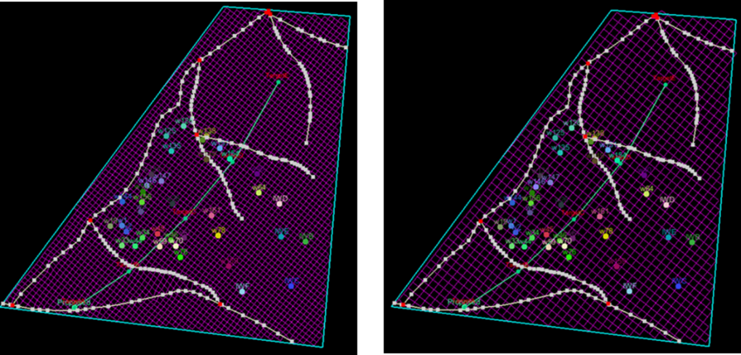
Fig. Original grids (left) vs. Up-scaled grids (right, with regular grids)
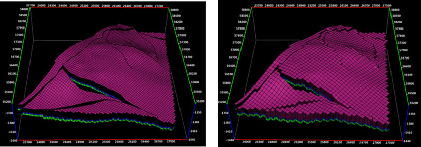
Fig. Original structure model (left) vs. Up-scaled structure model (right, with regular grids)
Steps to perform Scale Up Structure in GES:
· Go to Model pane → Click the model you want to scale up
· Go to Geology & Modeling Scenario → Reservoir Modeling → Model Upscaling → Click CornerPoint Gridding, a 2D window will be displayed → Click Create corner point grids → Input Grid Name → set I/J Increment → Click OK
· Click the new grid → Click Scale up Structure → Select data for Source Model → Click Source Model → Click OK
Scale Up Property
When the structure model has been up-scaled, property model can also be up-scaled and populated to the new property model.
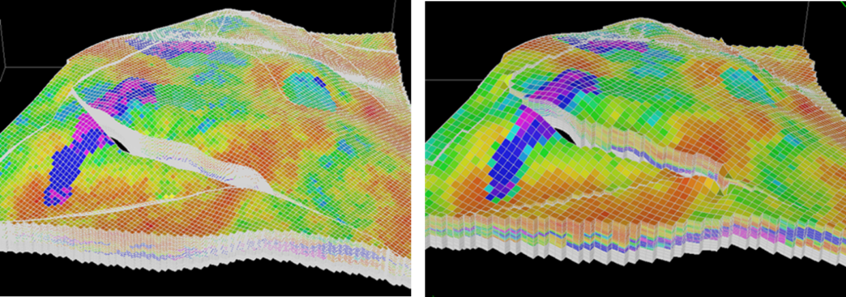
Fig. Original porosity model (left) vs. upscaled porosity model (right)
Steps to perform Scale Up Property in GES:
· Click the new grid → Click Scale up Property → Select data for Source Model
· Select property model you want to scale up for Property Model (Source) → Input property name for Property Model (Scale up) → Click Add
· Select algorithm for Scale up → Select Matching Method → Click OK
Structure Updating
The structure model local updating allows for a local update on horizon model, which alters grids as well. The input for structure model local updating includes well picks, point, line and surface data, fault polygons, and model boundary. Users may define the local update boundary by using a polygon; GES could also automatically identify the update boundary from the input data.
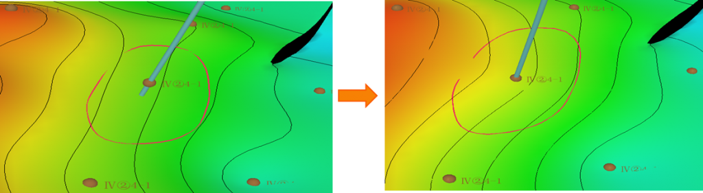
Fig. Structure map before updating (left) and structure map after updating
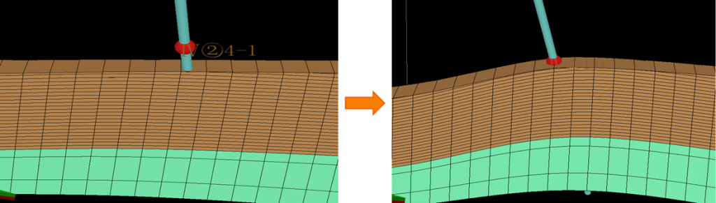
Fig. Grid model before updating (left) and grid model after updating
Steps to perform Structure Updating in GES:
· Go to Model pane → Click the model grid you want to updating
· Go to Geology & Modeling Scenario → Structure Modeling → Local Updating
· General Settings → Select data for Well Picks → Select data for Lines → Well Adjustment Settings → Regions Settings → Fault Lines Settings → Click OK
Block Well Updating
Block well local update is done in the Block Well window, users can update by adding and well settings.
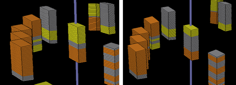
Fig. Local update on facies block well before updating (left) and after updating (right)
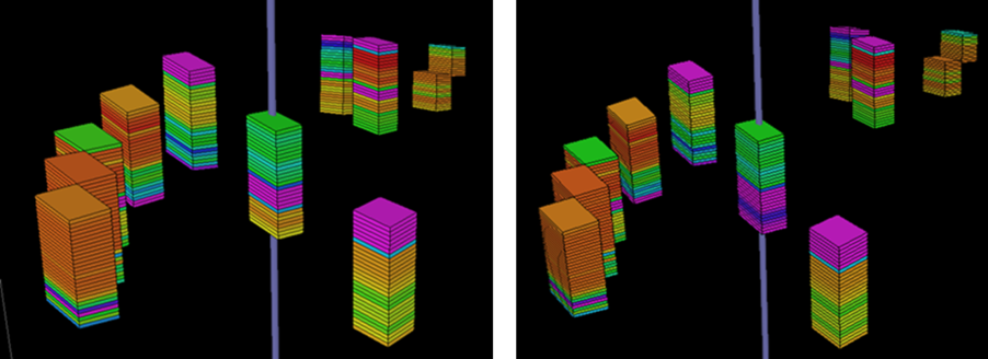
Fig. Local update on porosity block well before updating (left) and after updating (right)
Steps to perform Block Well Updating in GES:
· Go to Model pane → Click the model grid you want to updating
· Go to Geology & Modeling Scenario → Reservoir Modeling → Block Wells
· Choose block well you want to updating for BW Property → Click Add → Select Data Type and Data Name → Settings → Select → Click OK
Property Updating
Facies model local update allows users to update model within the volume defined by users. In GES, updating range are determined by 3 regions, well region, facies region, polygon region, you can choose to use intersection region, or use union region.
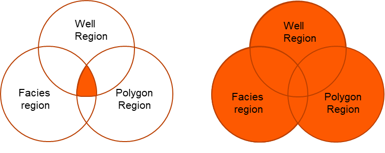
Fig. use intersection region (left) and use union region (right)
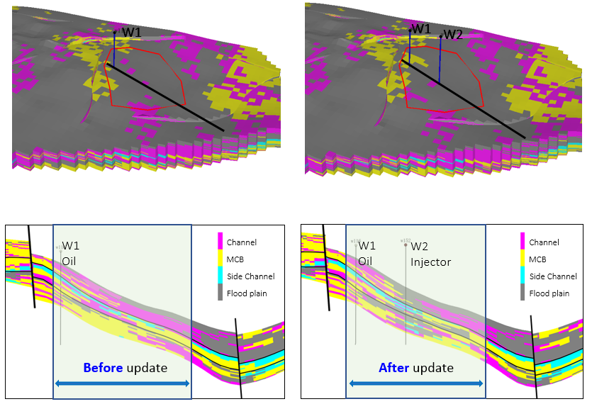
Fig. Facies local update (with a new well data)
Steps to perform Property Updating in GES:
· Go to Model pane → Click the model grid you want to updating
· Go to Geology & Modeling Scenario → Reservoir Modeling → Facies Modeling → Select data for BW Property Name → Input Model Name → Local Update Settings → Select updating region → Click OK
· Go to Geology & Modeling Scenario → Reservoir Modeling → Petrophysics Modeling → Select data for BW Property Name → Input Model Name → Local Update Settings → Select updating region → Click OK
Fluid Contact
Before setting fluid contact parameters, a detailed analysis is required to understand fluid contact(s) for individual fault blocks and zones. Once fluid contacts have been identified, you can set fluid contact parameters in the model.
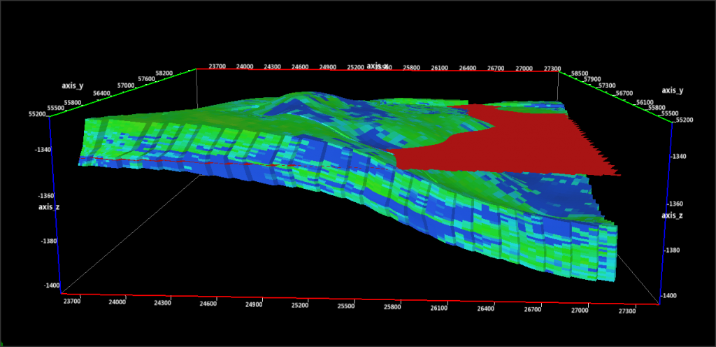
Fig. A fluid contact (red surface)
Steps to perform Fluid Contact in GES:
· Go to Model pane → Click the model grid you want to updating
· Go to Geology & Modeling Scenario → Reservoir Modeling → Fluid Contact
· Click Add → Input Name → Set Range Type → Setting for zones or fault blocks → Click OK