GES Modules
Structure Modeling
Structure modeling defines the top, base, fault surfaces and volume for each zone. It includes fault modeling, horizon modeling, and layering. Based on the nature of structure modeling, GES streamlines structure modeling into 5 steps: fault modeling, CornerPoint Gridding, horizon modeling, subzone modeling, and layering.
Fault Modeling
Fault modeling uses fault surfaces to represent the spatial distribution of fault zones. Fault modeling in GES can be built by fault sticks, fault lines, fault polygon and fault points.
· Fault Modeling created by fault sticks
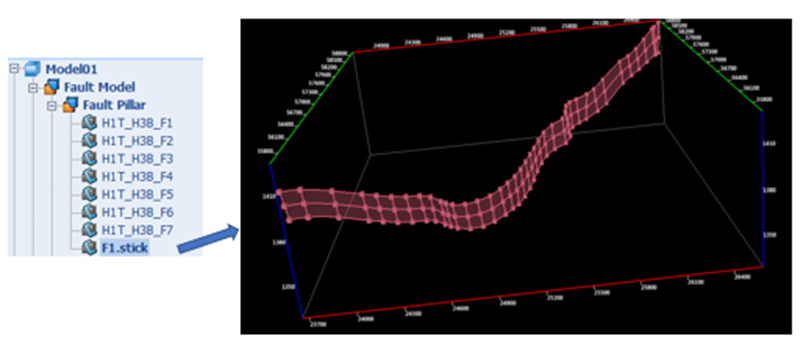
Fig. Fault pillar created by fault sticks
Steps to perform Fault Modeling (created by fault sticks) in GES:
Go to Geology & Modeling Scenario → Structure Modeling → Create Model → Input Model Name → Click OK
Go to Model pane → Click the model just created → Go to Data Pane → Faults → Fault sticks → Left click the sticks used for creating model → Right click → Create Fault Model → Settings → Click OK
· Fault Modeling created by fault lines (Fault)
Steps to perform Fault Modeling (created by fault lines) in GES:
· Go to Geology & Modeling Scenario → Structure Modeling → Create Model → Input Model Name → Click OK
· Go to Model pane → Click the model just created → Go to Data Pane → Faults → Fault lines (Fault) → Left click the sticks used for creating model → Right click → Create Fault Model → Settings → Click OK
· Fault Modeling created by fault lines (Horizon)
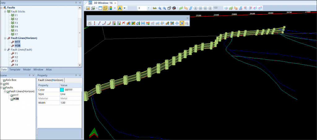
Fig. Fault pillar created by fault lines (Horizon)
Steps to perform Fault Modeling (created by fault lines) in GES:
· Go to Geology & Modeling Scenario → Structure Modeling → Create Model → Input Model Name → Click OK
· Go to Model pane → Click the model just created
· Go to Data Pane → Faults → Fault lines (Horizon) → Open a 3D window → Click one fault lines (Horizon) → Hold down shift on the keyboard → Click other fault lines (Horizon) used for creating model → drag selected fault lines (Horizon) to 3D window
· Go to Home ribbon bar → Edit Tools → Click Fault to show fault editing tools
· In 3D window, click a fault line (horizon)→ hold Ctrl on the keyboard → Click another fault polygon that belongs to the same fault surface → Click Create Fault Pillar with Polygon
· Fault Modeling created by fault points
Steps to perform Fault Modeling (created by fault points) in GES:
· Create a fault surface: Go to Home ribbon bar → Make Surface → Check Points → Select fault points used for creating fault model → Choose Boundary → Grid Settings → Algorithm Settings → Click OK
· Go to Geology & Modeling Scenario → Structure Modeling → Create Model → Input Model Name → Click OK → Go to Model pane → Click the model just created
· Go to Data Pane → Surface →Select fault surface just created →Go to Structure Modeling ribbon bar → Fault Modeling → Use Fault Surface → Click OK
CornerPoint Gridding
The purpose of creating CornerPoint grids is to establish a model boundary, I and J directions, and create corner-point grid framework.
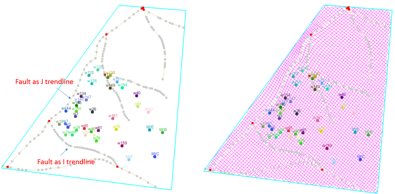
Fig. I and J trendlines (left) and grids created based on the trendlines (right)

Fig. Faults (left) and using faults as segment boundary to create fault blocks (right)
Steps to perform CornerPoint Gridding in GES:
· Finish Fault Modeling
· Go to Model pane → Click the model →Click CornerPoint Gridding on Structure Modeling ribbon Bar, a 2D window will be displayed
· Active the toolbar of the 2D window →Create a closed boundary →Define I/J direction →Click Create corner point grids → Input Grid Name →set I/J Increment →Click OK
Horizon Modeling
The previous section shows how to create skeleton grids. Skeleton grids are important to control the quality of 3D grids, but are not actual 3D grids. Horizon modeling utilizes horizon data (usually from seismic) and well picks to generate 3D grids for the key zones specified by users. Meanwhile, horizon modeling updates the skeleton grids of the top, middle, and base horizons.
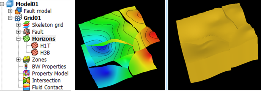
Fig. Horizon modeling results
Steps to perform Horizon Modeling in GES:
· Finish Fault Modeling and CornerPoint Gridding
· Go to Model pane → Click the grid just created → Click Horizon Modeling on Structure Modeling ribbon Bar
· Horizon settings: Add Row for each zone or Batch Select Data → Select data for Well Picks for each zone → Select methods for Algorithm Settings → Fault Settings → Well Settings
Subzone Modeling
After horizon modeling, a framework only include Zone modeling builds Geo-cellular models for the zones among key horizons.

Fig. Subzone modeling results
Steps to perform Subzone Modeling in GES:
· Finish Fault Modeling, CornerPoint Gridding and Horizon Modeling
· Go to Model pane → Click the grid just created → Click Subzone Modeling on Structure Modeling ribbon Bar
· Select Zone → Add Row → Select Data Type and Data → Click Apply → Move to the next zone and repeat the above steps until the isochore for all sub-zones are calculated.
Layering
After subzone modeling, the target model only have one layer for each zone, which cannot appropriately describe the heterogeneity of a reservoir. Therefore, creating layers in each zone is important. There are 4 layering methods:
• Number of Layers: Number of layers for each zone. The thickness of each layer belonging to the same zone is the same.
• Proportion: Define the individual percentage of layer thickness to the zone thickness. For example, 1,2,1 means there will be 3 layers, and the middle layer has a thickness twice as large as the top and base layers.
• From Top: Define the thickness of layers. From top to base, the software creates layers with the same thickness.
• From Base: Define the thickness of layers. From base to top, the software creates layers with the same thickness.
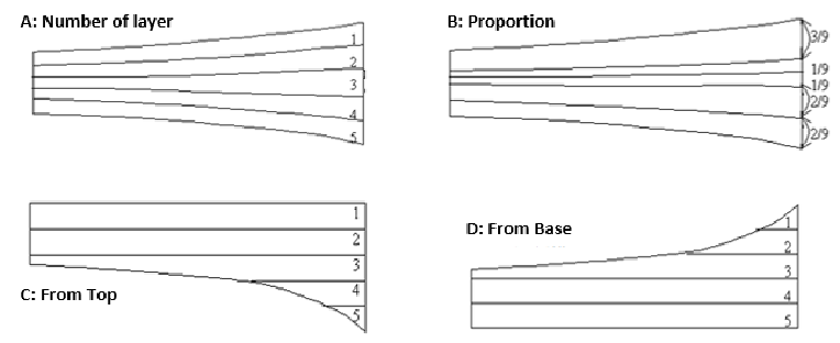
Fig. Visualization of layering methods
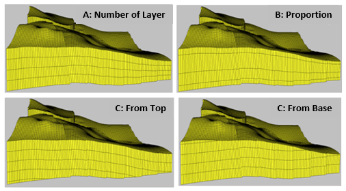
Fig. Examples of layering methods
Steps to perform Subzone Modeling in GES:
· Finish Fault Modeling, CornerPoint Gridding, Horizon Modeling and subzone modeling
· Go to Model pane → Click the grid just created → Click Horizon Modeling on Structure Modeling ribbon Bar → Select Layering Method → set Number for each method according to Method Description → Click Layering

